My process
I began by brainstorming simple Arduino projects that I could build with the components available in class. Because I am interested in cars and engineering, I decided to make a parking sensor that uses lights and sound to show how close an object is. I could test it by moving my hand toward the sensor and observing its response. This project built on the breadboard wiring and Arduino coding we practiced in class.
After choosing the idea, I searched online and found SunFounder’s Parking Sensor tutorial. I read through its explanation and studied the wiring diagram to understand how the ultrasonic sensor, LED, and active buzzer connected to the Arduino. Then I collected an Arduino Uno, a breadboard, an ultrasonic sensor, a red LED, a resistor, a buzzer, and jumper wires.
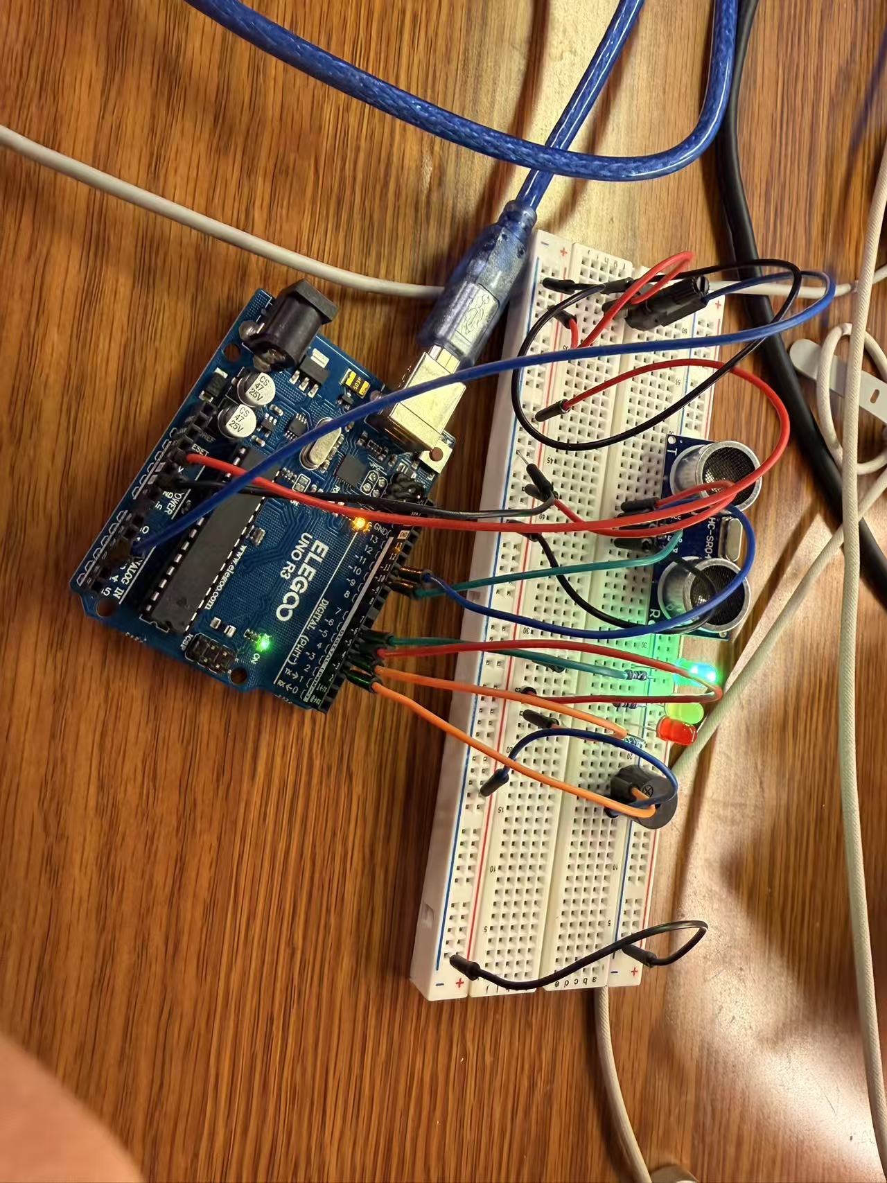
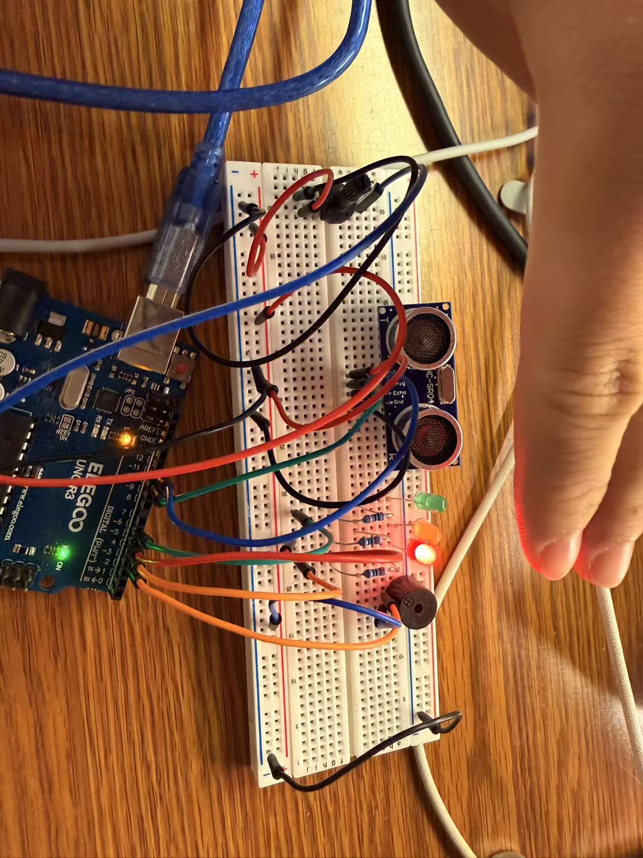
I started wiring the basic circuit by following the diagram. I connected the sensor’s power and ground, then connected its TRIG and ECHO pins to D11 and D10. I connected the buzzer to D3 and wired the LED through a resistor to limit the current. Each LED needs a complete current path from an Arduino output pin, through its resistor and LED, back to GND. Breadboard rails distribute power, while connected hole groups join component legs and wires.
While developing the circuit, I asked for feedback. Mr. Raus suggested adding a potentiometer so the user could adjust the buzzer’s behavior. Bruce Xie suggested adding yellow and green LEDs instead of only having a red light when an object got close. His idea would give the person parking more information about the distance. I used both suggestions to extend the original tutorial.
I added the yellow and green LEDs, giving each LED its own 1 kΩ resistor. My final pin assignments were green on D6, yellow on D5, and red on D4. I also connected the potentiometer’s middle terminal to A3 and its outer terminals to 5V and GND.
Once the components were connected, I asked Codex to help write and explain the Arduino code. The program reads the distance, selects an LED, and controls the buzzer’s timing. It uses digitalWrite() to set the LED outputs HIGH or LOW according to distance. It also reads the potentiometer to adjust the beep speed. I learned that an active buzzer has a built-in oscillator, so this version changes the timing of the beeps rather than their musical pitch.
Getting everything working required troubleshooting. An incomplete copy of the sketch caused a missing-brace error, so I replaced it with the complete code. I also encountered upload errors when the selected USB port was no longer available. These problems taught me that compiling and uploading are separate steps.
When the LEDs and potentiometer seemed unresponsive, we checked the pin assignments and used Serial Monitor to inspect the distance and A3 readings. I learned to test the potentiometer with an object in the beeping range, because turning it would not produce an audible change when the buzzer was silent or sounding continuously.
The resulting code uses green above 17 cm, yellow above 9 cm and up to 17 cm, and red at 9 cm or less. Green indicates a farther distance, yellow provides a warning, and red indicates that the object is close. The buzzer beeps faster as an object approaches and sounds continuously at 5 cm or less. Through this process, I learned how to develop a tutorial into my own interactive design, use feedback to improve it, and troubleshoot the hardware and code together.
My circuit in action
These photos show my actual breadboard circuit during testing. Select either photo to see it at full size.
View my complete Arduino code on GitHub.
Technical Tidbit
The ultrasonic sensor measures the travel time of sound. According to the HC-SR04 datasheet, a trigger pulse of at least 10 microseconds starts eight cycles of 40 kHz ultrasound. The ECHO pulse represents the sound’s round-trip travel time.
Sensor → sound → Object
Sensor ← echo  ← Object
Distance equals travel time multiplied by the speed of sound, divided by two because the sound travels out and back. My code uses the approximate conversion duration / 58.0 to calculate centimetres. For example, 580 microseconds corresponds to about 10 cm.
The potentiometer provides an analog voltage, which analogRead(A3) converts to a value from 0 to 1023 on my Uno. A digital input is read as HIGH or LOW; pulseIn() measures how long the sensor’s digital ECHO signal stays HIGH.
Peer support
Bruce Xie suggested adding yellow and green lights so the person parking could understand the distance better than with a single red light. His feedback helped me think about how clearly my device communicates information. I added the two LEDs and updated the code to show different distance ranges.
Next time, I plan to ask a classmate to try my device and explain what they think the signals mean, and offer the same feedback on their project.
Use-case reflection
This device could help a driver judge the distance between a car and a garage wall. To make it useful outside the classroom, I would add secure mounting, a protective enclosure, and warning distances suitable for a vehicle. I would keep red for the closest range and add a separate warning when the sensor cannot get a reading.
The skills I would rely on most are debugging and wiring. Testing the sensor, lights, and buzzer separately would help me identify problems and improve the device’s reliability. Next, I would explore using the potentiometer to adjust the warning distance instead of beep speed.